")
")
")
 Line
Line
Double click on the icon opens the parameter dialog: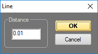
It is possible to specify a minimal length here. When tracing logos, this value should be rather low.
The line tool is used for drawing ordinary lines. The first click sets the start point, any further clicks set new end points, starting from the previous point. Normal lines are drawn on left click. Right click draws blanking lines. Click on the middle mouse button (or scroll wheel) draws color gradients. Spline
Draws a spline
Double click on the icon opens the parameter dialog: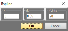
Specify curve values and point density here.
The first click sets the start point. then click the center of the spline and hold the mouse button to modify the spline. Release Freehand
Free hand drawing. Left click, hold and drag. Points are set automatically. A right mouse click sets a blanking point. Rectangle
Double click on the icon opens the parameter dialog: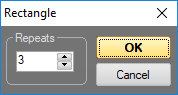
Specify the numer of corner point repetitions here.
Click and drag with left mouse button draws a square.
Click and drag with left mouse button draws a rectangle. Circle
Double click on the icon opens the parameter dialog: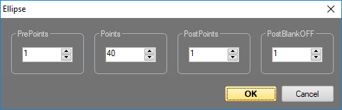
Specify the number of blanking points before and after drawing a circle as well as the overall number of points to be drawn. The smaller the circle, the smaller can be the number of points.
Click and drag with the left mouse button draws a circle.
Click and drag with the left mouse button draws an ellipse.
On additionally pressing SHIFT or CTRL it is possible to draw half circles. X Corners
Double click on the icon opens the parameter dialog. It looks similar to the spiral dialog.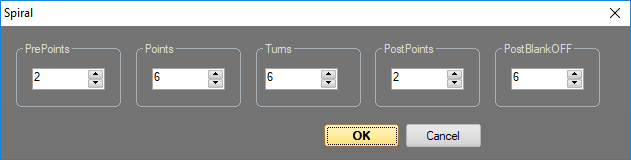
Important here is the number of points.
Click and drag creates polygons. Depending on if left or right mouse button is used, it's either a symmetrical or asymmetrical shape. Spiral
Double click on the icon opens the parameter dialog, siehe X-Corners.
Set point number and number of turns.
Click and drag with the left mouse button to create a Spiral. Text Tool
Select the tool and click to the position where the text shall begin.
A dialog opens to specify the text and the font.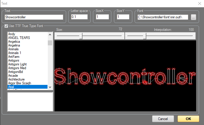
It is also possible to specify size and interpolation steps here. Laser-optimized fonts can be used as an alternative to TrueType fonts. Those usually lead to better output results. Point Tool
Creates single beams. Increase intensity by setting several points at the same position.
Selection:
After having drawn an object, it is possible to select complete objects or single points for further editing. All functions apply to the previously selected (active) points. All points can be selected by using the key "A". With using key "I" all selected points becomne inactive/deselected.
Selected points are marked in color. Selection Tool
When having selected this tool, left click and drag a selection frame around the points to be selected. On release of the mouse button all points within the selection frames become active and corlo marked. Select Object Tool
This tool allows for selecting a complete object on left mouse click. Click with right mouse button sets the object selection to inactive.
Transformation:
After an Object (or points) has been selected it can be rotated, moved or altered in size.
These are the tools to do so: 
1. Move Point only moves the next point.
2. Move moves the selected object
3. Scale scales the selected object. Click with left mouse button to specify the center and drag with clicked mouse button to scale the selected object.
4. Rotate rotates the selected object. Click with left mouse button to specify the center and drag with clicked mouse button to rotate the selected object.
Keyboard shortcuts:
"M" = Move
"S" = Scale
"R" = Rotate
It is possible to modify the selected object using the cursor keys in these three modes. Additional pressing of SHIFT or CTRL changes the step size.
Views:
Change the view of the active working area: Front, Side, Top: 
Lock Axis:
It is possible to lock the third axis, depending on the actual drawing mode. Click on the icons  to do so, or use the keys X,Y or Z.